

A newly installed LED grid screen can pass a simple light-up test and still show the wrong picture. An animation may travel backward across one facade bay, a logo may jump at a module joint, or one section may display content intended for another floor. These faults are especially visible on large media facades, where physical modules are assembled in a repeating grid but the control system must address every pixel in the intended order. Contractors need a commissioning method that compares the approved layout, actual wiring, and controller mapping before the final advertising content is accepted.

Why Do Large LED Grid Screens Develop Mapping Errors?
A display contains a physical arrangement of lights and a digital description of where those lights belong. If the two arrangements disagree, the picture appears misplaced even when individual LEDs function normally.
What Is the Difference Between a Wiring Fault and a Mapping Fault?
A wiring or communication fault may leave a section dark, intermittent, or unresponsive. A mapping fault can leave the LEDs illuminated but assign them the wrong image coordinates. Swapped output routes, a reversed module orientation, incorrect addressing, or an outdated facade drawing can produce similar-looking image breaks. Before replacing parts, run a simple test pattern and check whether the same section responds consistently to its assigned controller output.
Why Are Irregular Facades More Difficult to Commission?
Glass bays, corners, curved elevations, and open areas may interrupt an otherwise rectangular display. A content file can be perfectly rectangular while the actual screen includes gaps or modules installed in different directions. Those interruptions must be represented in the pixel map rather than ignored. Record each physical zone with a stable identifier; do not rely on installers remembering how an upper-floor segment was connected.
What Should Be Checked Before Software Calibration Begins?
Mapping software cannot compensate for a wrong hardware inventory. First confirm that installed modules match the approved drawings and that every section is assigned to the intended physical zone.
How Should Contractors Verify Module Orientation and Addressing?
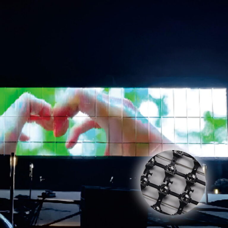
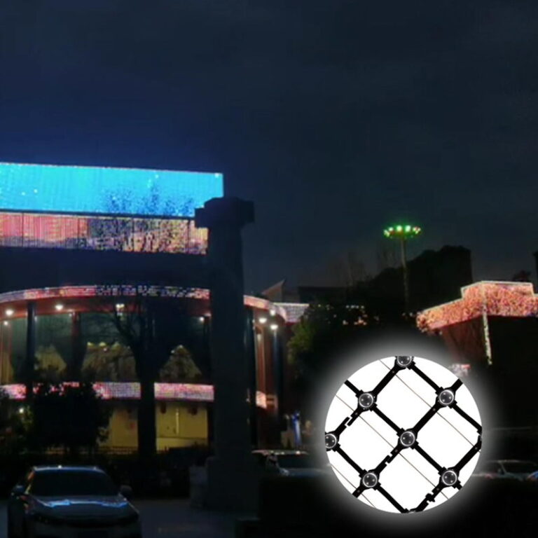
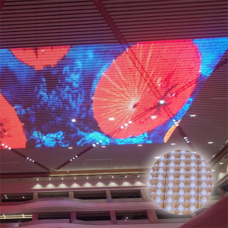
Use the site elevation to check the start point, horizontal and vertical direction, module numbering, data-entry side, and output route for every facade section. Mark any changes made during installation and update the as-built drawing. Xinhe’s giant LED grid screen series includes modular products with different pixel arrangements and control configurations, so the commissioning file must follow the exact supplied hardware rather than a generic template.
Which Control Details Must Match the Actual Product?
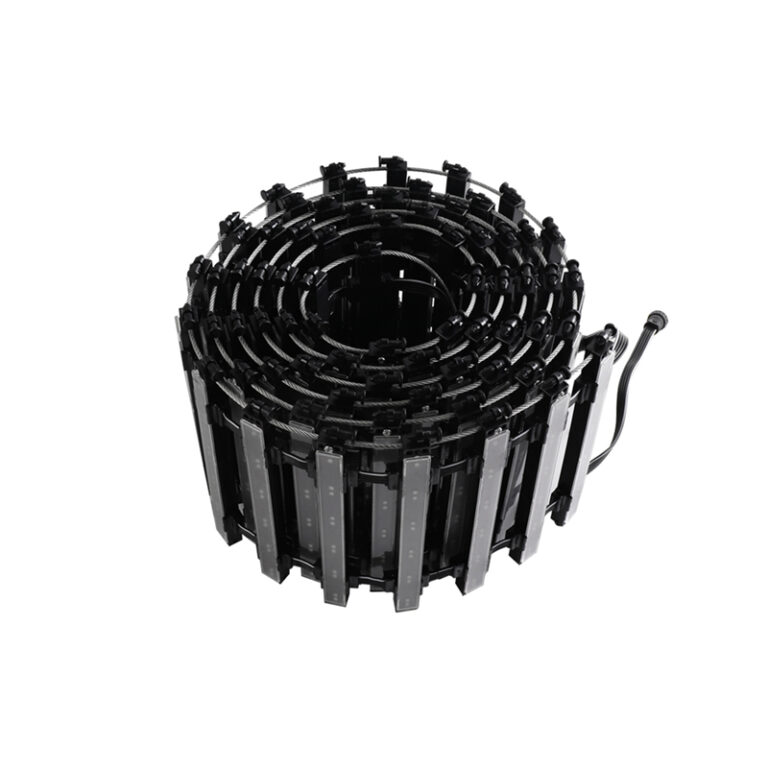
For example, the XH-star H2503 LED Grid Screen is listed in RGB, RGBW, and other version-dependent configurations, with DMX512 or an alternative signal arrangement depending on the model. Verify the selected variant, controller documentation, channel or pixel addressing, and output limits before loading a mapping file. An RGBW configuration cannot safely be commissioned using assumptions copied from a different RGB setup.

How Can Test Patterns Reveal Image Alignment Problems?
A full-motion advertisement is a poor first test because rapidly changing content can conceal which section is misplaced. Start with deliberately simple patterns that make location and direction obvious.
Which Patterns Should Be Used First?
Display a single moving point, a numbered zone map, horizontal and vertical lines, and a slow color sequence. Move the point from the designated origin to the opposite corner, checking it against the as-built drawing. Straight lines reveal offsets or reversals between adjacent modules; numbered zones reveal swapped outputs. For a curved or multi-plane facade, test each plane independently before checking the complete composition.
How Should Contractors Record Defects During Testing?
For each discrepancy, photograph the displayed pattern, note the module or zone identifier, and record the controller output and current mapping version. Separate hardware faults from configuration faults in the punch list. If the error follows the same physical section when a pattern changes, investigate its addressing and signal path. A repeatable record makes corrective work faster and avoids retesting an entire facade after every small change.
How Should the Final Content Be Aligned Across Module Boundaries?
Once basic addressing is correct, the content team should test the kinds of images the site will actually display. Building features and viewing angles can make apparently aligned graphics look distorted from the public viewing position.
What Should Be Tested at Normal Viewing Distance?
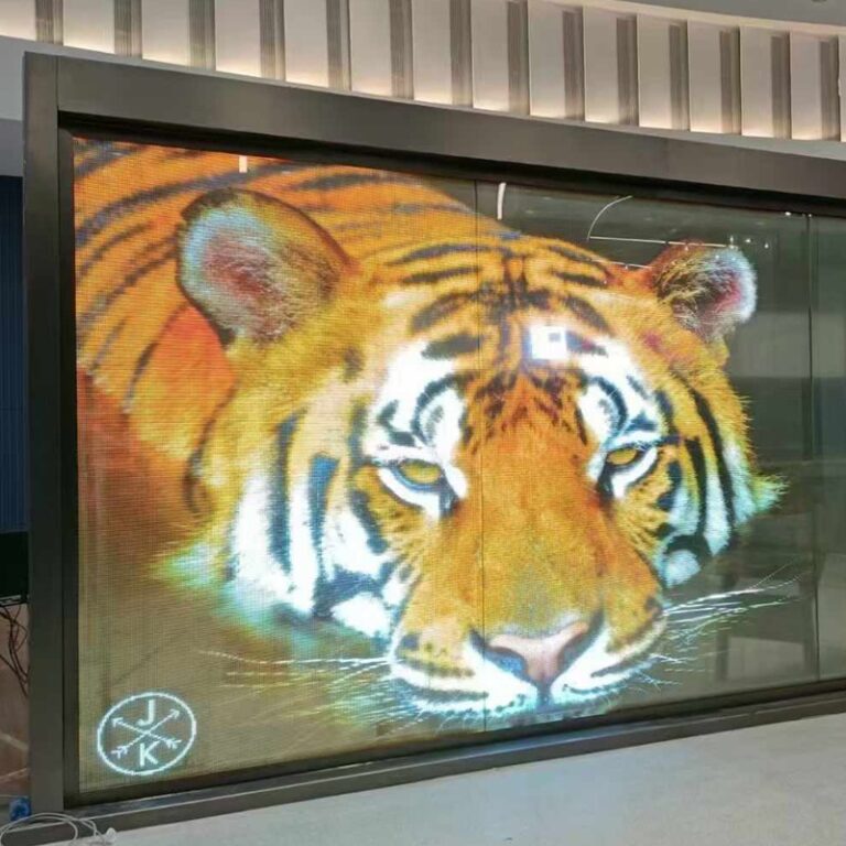
Use large text, a moving logo, faces where appropriate, and slow horizontal motion. Confirm that the image crosses seams in the intended direction and that essential information does not disappear behind structural gaps. For a facade viewed from a plaza, stand at the principal viewing location rather than evaluating alignment only from a laptop near the controller. Brightness and color uniformity can be checked during this stage, but they should be logged separately from mapping errors.
When Should the Mapping File Be Frozen?
After the contractor, integrator, and owner approve the test sequence, save a named final configuration and an annotated as-built layout. Preserve a backup of controller settings and identify who may change them. If a module is replaced later, the maintenance team needs to know its physical coordinates and configuration; otherwise a routine repair can reintroduce a visible image fault.
Why Work With Xinhe Optoelectronics for Grid Screen Projects?
Shenzhen XinHe Lighting Optoelectronics Co., Ltd. has supplied point-light and grid-screen products for architectural lighting since 2004, alongside design and on-site project support. Its published grid-screen specifications identify pixel spacing, control options, and modular installation features that contractors can use to build a project-specific commissioning checklist. The company also publishes architectural lighting project cases that illustrate the scale and setting of facade work. Reviewing those details against the installed model is more dependable than treating all mesh facades as one control format.
Conclusion
Reliable LED grid screen pixel mapping begins with an accurate as-built module map, verified control settings, and simple location-based test patterns. Contractors should correct physical and addressing mistakes before fine-tuning the artwork, then confirm alignment from the intended public viewing positions. A signed-off mapping file and zone record make both handover and future repairs easier.
FAQs
Why does one section of my LED grid screen display the wrong image?
The physical module order may not match the controller map, or a data route may be assigned to the wrong zone. Verify orientation, addressing, and the as-built output map with numbered test patterns.
Can a test video replace a pixel mapping checklist?
No. A video may conceal reversed or swapped modules. Begin with a moving point, numbered zones, and straight lines; use actual media only after those patterns pass.
What should be handed over after commissioning?
Provide the final mapping and controller files, an as-built module schedule, labeled zone drawings, a defect log, and approved test images for later service work.






 English
  Arabic
  Russian
  Spanish
  French